A Raspberry Pi-based device that scans a QR code on the bottom of a spice container using the OpenCV library and reads out the name of the spice for visually impaired chefs

Skills Developed
• Python 3 programming
• Simple Linux commands
• OpenCV Python library
• Playsound Python library
• Designing Gantt charts
• IEEE (Institute of Electrical and Electronics Engineers) citation guidelines
Summary
ENGINEER 1P13 is a course that all first year Engineering students at McMaster University must take. While I have worked as a TA for this course in the past, there was once a time where I was in my first year of Engineering, and I had to take ENGINEER 1P13. This course runs for the full school year, and has more credits that four regular courses. ENGINEER 1P13 exposes all first year Engineering students to a variety of engineering skills such as computer programing, modelling using CAD software, materials science, prototyping, 3D printing and the legal requirements of ethical engineering. This course is centered around four group projects that aim to prepare students to someday practice as engineers while helping to narrow down which Engineering specialty students want to pursue. I wanted to highlight project four since at the time of completion, the final product of this project was easily the coolest thing that I had ever helped to create.
The fourth and final project was called “Power in Community”. The timing of this project overlapped slightly with the final weeks of project three. For this project, I was placed in a group with three other students. I assumed the role of project administrator, since this was the only role that I had yet to fulfil. As administrator, I was tasked with submitting assignments to the drop-box. Project four involved our group designing something to help one of two clients, who were a married disabled couple. The Engineer 1P13 class met with our clients twice over Zoom to ask them some questions about their conditions and help brainstorm ways to help them. In the interest of respecting their privacy and being professional, I will not use their names.
The gentleman is blind, but he can still somewhat discern light from darkness. He uses a cane. Our male client enjoys cooking, but he makes quite a mess. He is good at determining the material of things with either his feet or his cane (except when everything is covered in snow). His blindness is the result of him being a type I diabetic who suffers form diabetic retinopathy. He uses Dexcom and Libre glucose monitors. The lady cannot turn her head to the right. She has multiple sclerosis and uses a powered wheelchair. The husband grabs on to his wife's wheelchair when they go out together. In the early weeks of project four, my groupmates and I had to research various topics relating to project four. I chose to research existing solutions. My research document can be found here. Project four was also unique because students in the Faculty of Science would review our design. Below are the objectives for project four [1].
Project four was easily the most open-ended of all the projects in Engineer 1P13. While previous projects had a lengthy list of restrictions on our design, the only real constraint for project three was to not spend over $100 on the parts that would be used. We could design anything, be it a software, a physical object, or a combination of the two. Initially, I wanted to design a double spatula since our male client likes to cook. Double spatulas are widely used by visually impaired chefs because they combine the function of tongs with a spatula. However, these utensils cannot perform the same functions as standalone spatulas or tongs. Unlike every commercially available double spatula that I saw, my design would have the sides of the spatulas ruffled to make the device function more like tongs, and to make the preparation of pasta and noodles easier. Additionally, I planned on making the two halves of the device detachable to avoid the common problem of the upper half of a double spatula colliding with and destroying foods when the device is used as a spatula. Some of my early designs can be seen below.
During the second week of project four, I met with my group to discuss what we would create. As mentioned earlier, our blind client like to cook. Spices are typically sold in identical containers, and due to our client’s diabetes, they lack the sensitivity in their hands to read braille. This means that in order to differentiate between spices, our client must unscrew the lids to their spice containers. This can be messy, unsanitary and time consuming. Furthermore, our client must struggle tremendously with identifying odorless spices such as salt. Similar to project three, our solution had to be creative. Our group agreed that we would design a device that would help our client differentiate between spices by playing audio files.
The device would work as follows. A camera would scan a QR code stuck to the bottom of a spice container. This QR code would be mapped to an audio file which will play the name of the spice. The program that would make this all possible would be written on a Raspberry Pi. There would be two main sub-teams for project four. There would be a modeling sub-team that would make the casing to hold the necessary hardware in place, and there would be a computing sub-team which would write the program. My teammates wanted to add lights to the device, to ensure that the camera had enough light to detect the QR codes. Being the strongest programmer of our group, I would ultimately be the only member of the computing sub-team, and singlehandedly write every program used in project four in the Python language. All of the commands were written in Linux.
We spent quite a lot of time shopping for hardware components at the start of project four. There was a global semiconductor shortage at the time, so I had to reach out to my friend in second year IBIOMED to buy his Raspberry Pi. I had a cardboard box where I carried all of the hardware parts. I learned my lesson from project three to not haphazardly throw my important project materials into my backpack and hope that nothing gets destroyed. Below is a table showing the parts we purchased, where we purchased them from, as well as their prices. I would purchase all of the electronics that would ultimately be used in this project.
I ended up writing three programs. The first program controlled the lights and required sudo permissions. The second program was the program that controlled the speaker automatically on startup without a monitor connected to the HDMI port. This program could only output audio through a 3.5mm AUX headphone jack because of the manufacturer determined audio path priorities for that particular model of Raspberry Pi. The third program was quite similar to the second program. This third program was used during live demonstrations and debugging. It connected to a monitor with an HDMI cable, and could show a live view of what the camera was seeing in real time.
Immediately after turning on the Raspberry Pi for the first time, I noticed that the case that it came with could hold the fan above the heat sinks, but blocked the point of attachment of the camera. I immediately notified my groupmates who were in charge of modelling the housing for my hardware, and they set about designing a case that supported the fan and the camera.
Despite being probably the most experienced programmer in my group, I had only been programming in Python for less than a year at the time of this project. I was still quite new to the Python programming language. I used the following two video tutorials to help complete this project.
Although these tutorials proved to be quite helpful, they were still very different from what I intended to do with the Raspberry Pi. As will be explained soon, these videos served more as helpful suggestions than guides to follow.
After watching the tutorials, I had written the following program:
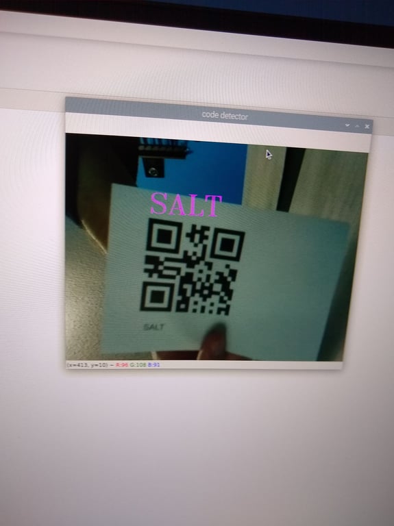
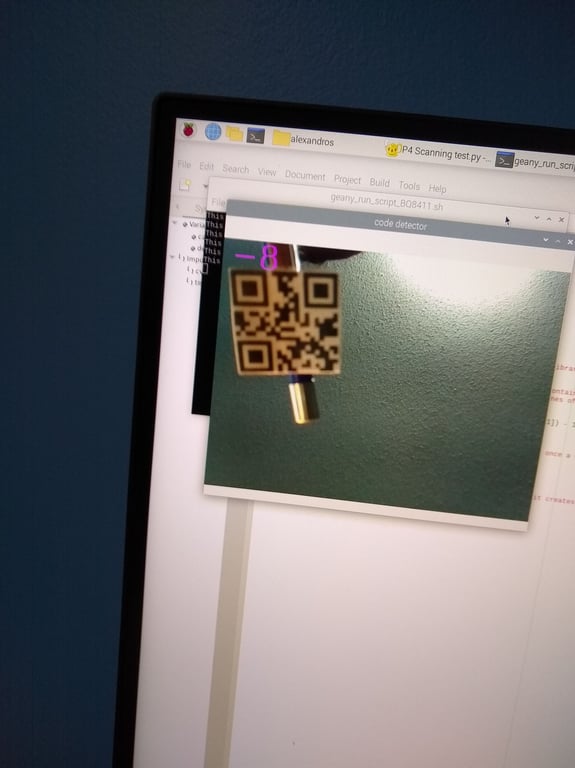
At this point, my program would constantly scan for QR codes. The information would be displayed in large magenta text above the QR code in the camera output window. Sometimes, my program would return an error when trying to draw the bounding box around the QR codes for analysis. When a QR code was found, the information contained within that QR code would be outputted up to 20 times per second in the shell. There was a output window which showed the live view of the camera in real time. The camera view had a blue tint to it and the associated libraries had to be updated, which can be seen below. Yes, this is my face.
To fix my code, the first thing I added was a time.sleep after each instance where a QR code was detected. However, this ended up causing problems. The last frame that the camera saw when it detected a QR code could be remembered sometimes up to 10 seconds after that QR code had been removed from the field of view of the camera. To fix this, I reset the camera view after every time.sleep. To fix the rare error that would occur when the program would draw the box around the QR code, I implemented a simple try-catch that would reset the camera view whenever this error would occur. Additionally I changed the number of the camera object from 0 to -1, since that proved to be a more reliable setting.
At this point, it was time to test my program with some QR codes. My original testing plan consisted of four QR codes of size 25 to 36 cm². Each of these QR codes scanned almost instantaneously, and the program worked perfectly. Below are my four original testing plans, and the output in the shell.
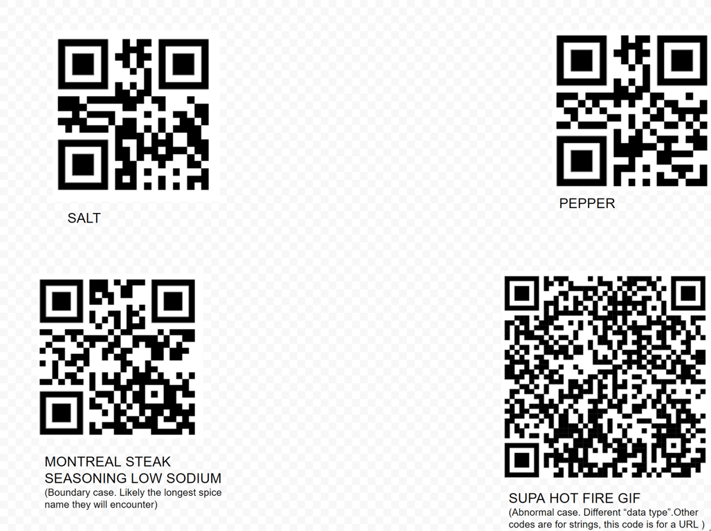
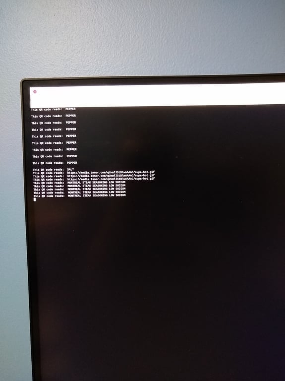
Here the results of the camera output window can be seen:
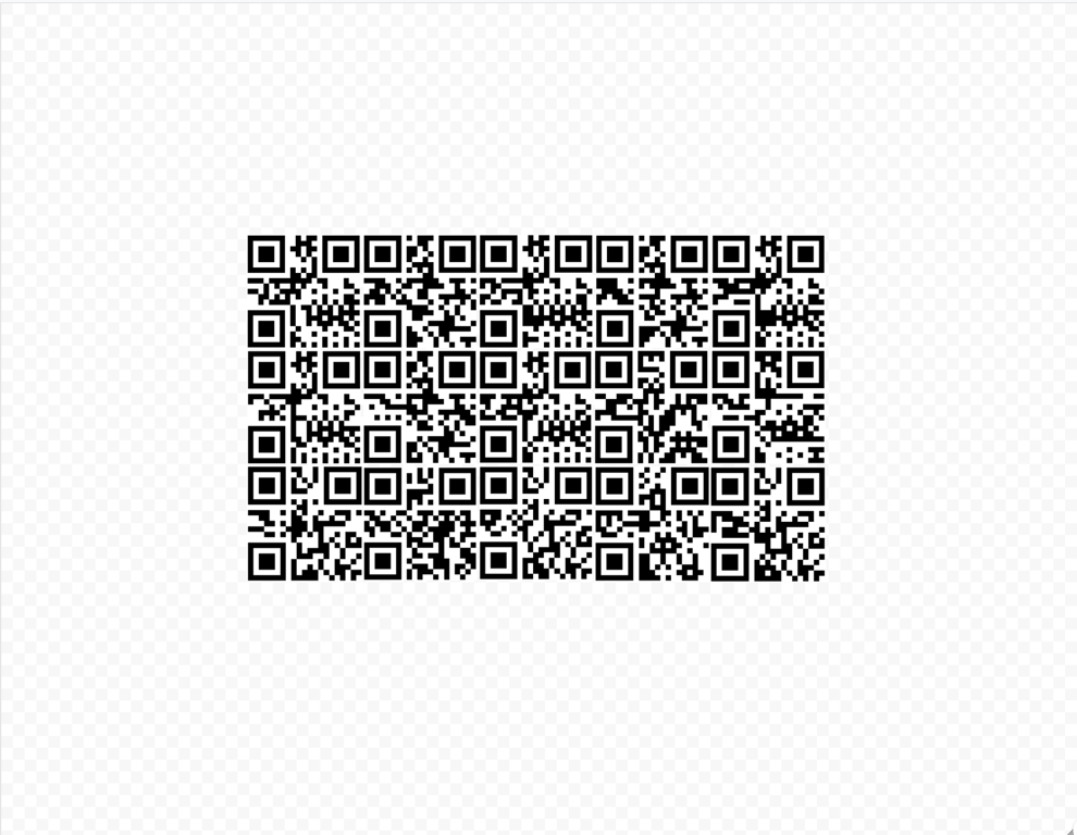
Although it was great that my four original testing plans all worked, the size of these QR codes was way too large to fit on any reasonably sized spice container. For my next testing plan I used only numeric strings, and I shrunk the footprint size down to 2.5 by 2.5 cm. Integer text strings were chosen for our second testing plan because they encoded for less data. Therefore, these QR codes could be made much smaller or scanned from further away since they lack small details which are difficult for the camera to discern. Originally, we had planned for each QR code to encode for the name of the spice to eliminate redundancy. Now, we decided to change the value encoded by each QR code from a text string to a integer string. The integer string could then be mapped to that spice’s audio file. Below is the second testing plan.
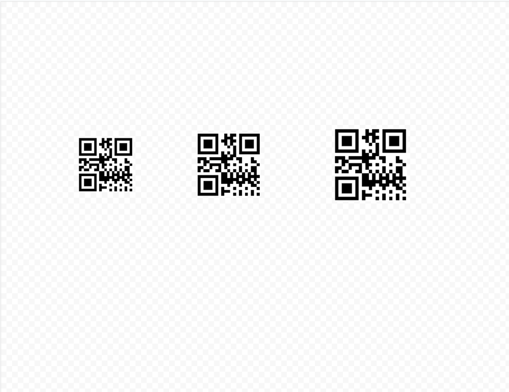
Although each testing case could be scanned, some of these cases took upwards of a minute before their names appeared in the shell. This is too long of a timeframe to be practical for our client. It had become clear that the ideal size for the QR codes had to be somewhere in between 2.5*2.5cm and 5*5cm. Our next testing plan involved three QR codes that encoded for the number “3”. The first QR code was 3*3 cm. The second QR code was 3.5*3.5 cm, and the third QR code was 4*4 cm.
At this point, I had become aware of a certain engineering tradeoff relating to the size of the QR codes. Smaller QR codes could be placed closer to the camera, which would reduce the size of the physical mechanism that the modeling sub-team would have to create. However, the camera used for this project was literally the cheapest camera that money could buy. The focus of the camera was not adjustable and set to an infinite distance. In order to be reliably scanned, a QR code had to be far enough away that the camera could make out the details necessary to read it.
After extensive experimenting, I had determined that the ideal size of a QR code was 3*3 cm. Using a meter stick and an eraser to hold the QR codes up, I determined that the ideal distance was 10 cm, but the minimum distance was 8 cm from the camera. The distance between the QR code and the camera could be reduced further by adding either a white or a blurred background. This makes sense because the camera is looking for black squares patterns within a white background, and a uniform, featureless background makes it easier for the camera to find these patterns.
With the results of my most recent test, I printed 15 QR codes of the numbers 1 through 15. Each QR code was 3*3cm.
It was at that moment that I realized that QR codes encoding for similar amounts of data could differ tremendously in the time that it takes for them to be scanned. For example, our fastest test cases, "3" and "1" could be scanned almost instantaneously. Our slowest test case, "2" could take up to 20 seconds to scan at a similar distance. For this reason, we would ultimately demonstrate the final design to our IAIs with the QR codes for “3” and “1”.
I also did some audio benchmark tests to see what volume the speaker should be set to , as it would be difficult to adjust the speaker volume during the interview for this project.
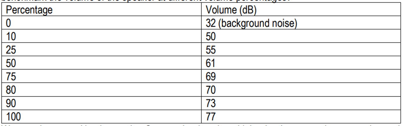
I determined that the speaker should be set to 80% volume since anything louder that that hurt my ears at a distance of 1 meter away. While I assume that our client has sensitive hearing, as many blind people do, the speaker would be loaded into a plastic case, which would slightly muffle the sound. Our device would be useless if the client could not hear the names of the spices. It is better to have the speaker be too loud than too quiet, Using the playsound library, I added 15 audio files for the names of 15 common household spices . These files would play when the correct QR code was brought into the field of view of the camera. The integers and their corresponding spices can be seen below.
- Salt
- Black pepper
- Garlic Powder
- Chili powder
- Onion powder
- Cinnamon
- Oregano
- Bay leaves
- Cumin
- Sage
- Montreal steak seasoning
- Cloves
- Nutmeg
- Ginger
- Paprika
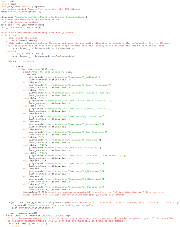
I made sure that each QR code had enough time to have its audio message be read. I coated each QR code in waterproof transparent tape to allow ensure that they would be able to last long in the chaotic, messy environment of a kitchen. Additionally I added an audio message that would prompt the user that the scanner is activated upon startup. I also added a message that would read " by the way, your scanner is still running" after one minute of inactivity. By this point, my program was identical to the demo program with an output window, which looked like this:
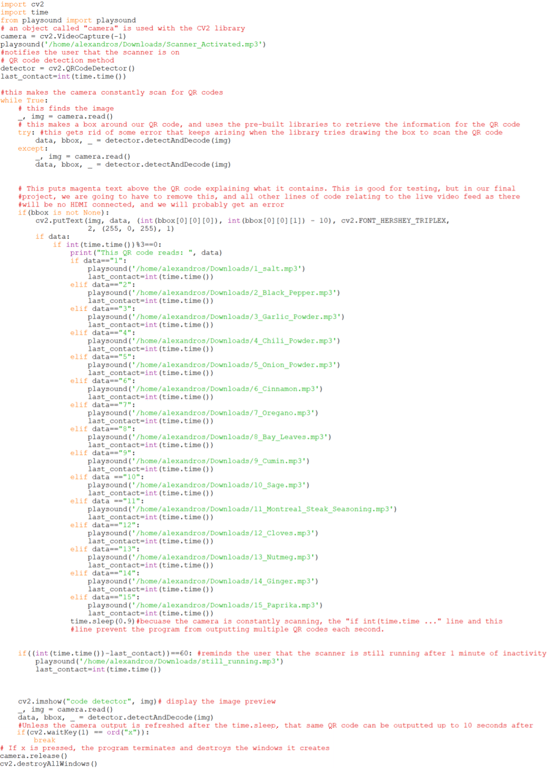
There were a few slight modifications that needed to be done to convert this program into the one that would run without a monitor automatically on startup. All of the lines of Linux code responsible for the live camera view window were removed. crontab –e was typed into the terminal followed by @reboot sleep 30 && python home/alexandros/Desktop/.py. This also ensured that the libraries required for this program had sufficient time to load. To run other programs, the user must enter sudo top into the terminal to see all actively running processes, then ctrl+c and then kill. As mentioned previously, the physical hardware had to be changed as well. The AUX speaker had to be used instead of the USB speaker. The automatic startup program can be seen below.
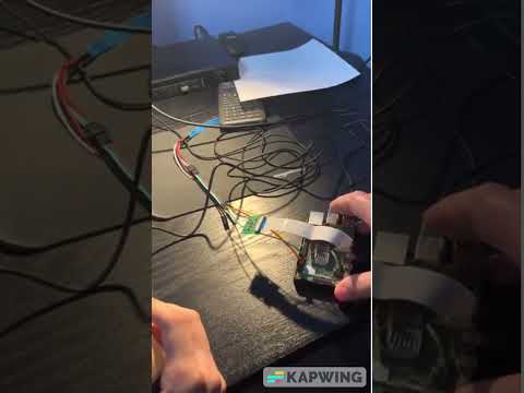
This program can be seen in action below. Note that I had to cut some footage because my project portfolio was originally created on an older version of Notion that did not allow video embeds, and limited video uploads to 5MB. Additionally, the quieter AUX speaker had to be used, and I end up getting interrupted by my idle message.
The final program that I wrote controlled the lights. This was an incredibly simple program that required sudo permissions to run. The IAIs were generous enough to do the necessary soldering. Given that this program required a different permission level than the other programs, it could not be run on startup like my group had originally intended (the playsound library would return an error). However, this program could still be run manually following the use of the aforementioned kill command in the terminal. The modelling sub-team had to be consulted to determine how many lights would fit inside of the footprint that they built for the camera since the lights that we purchased came in a roll of 60, and the number of lights that you needed could be cut out of the roll. We ultimately ended up using 2 lights. Below is the program that controlled the lights.
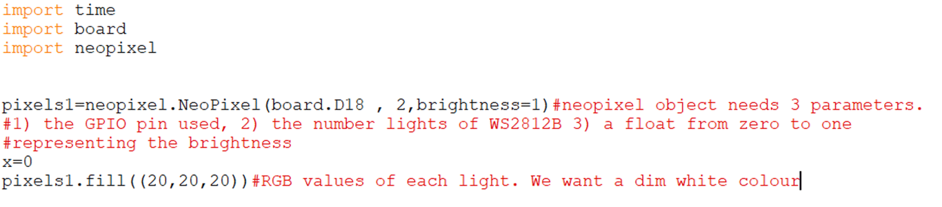
Changing the parameters in the last line can change the colour of the lights as well. Here are the lights in action:
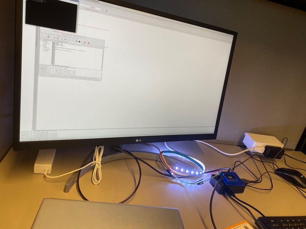
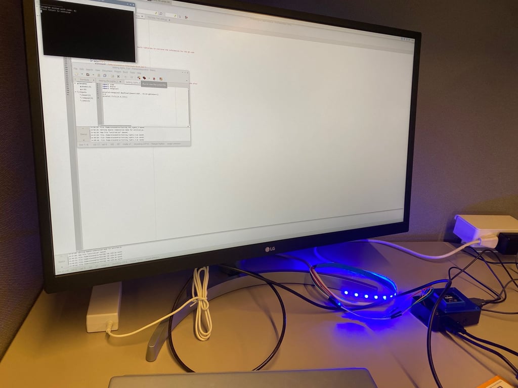
There was no room left in our budget for an on-off switch. Once the lights were turned on, they stayed on until the power supply of the Raspberry Pi is unplugged, or until the parameters in the final line of the lights program were set to (0,0,0. Some would consider this a defect, but I consider this a feature. Our client probably does not always turn on the lights whenever he enters a room. The camera needs light to scan the QR code, so it makes sense for the lights to always be on, especially considering that the client will be periodically reminded that their scanner is running anyways. Our final GPIO (general purpose input output) pin configuration on the Raspberry Pi can be seen below.
GPIO Pin | Purpose |
1 | Powers fan |
2 | Powers lights |
6 | Grounds lights |
12 | Gives information to lights |
14 | Grounds fan |
With all of our programs complete, my groupmates and I began creating the slideshow that we would ultimately use when presenting our final design to the IAIs. Although I barely contributed to the design of the physical casing, I would like to share a video of the exploded view of our device. The device is shaped like a coffee maker. The camera sits at the bottom with the lights and scans upwards towards the bottom of the QR code. The Pi is at the back, and the speaker is on top.

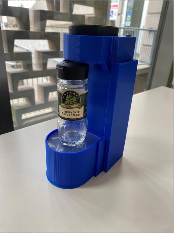
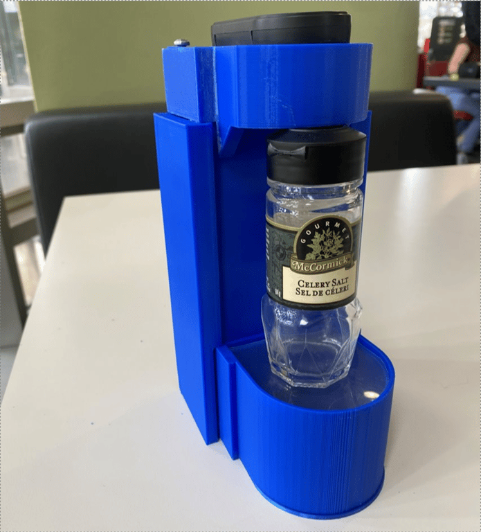
One of my groupmates came up with the idea to call the device “The Spice Savvy”. Here are some pictures of our 3D-printed final design.
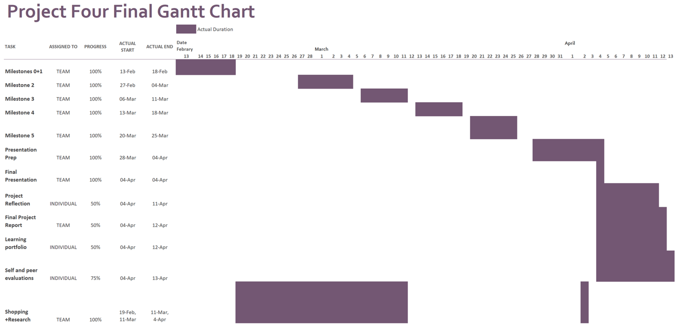
The presentation had a dress code that was as my teammate worded it “something in between business formal and business casual”. My groupmates and I showed up early to assemble our device. Our presentation went well. I did stumble a few times because my groupmates changed some of our slides at the last minute without telling me, but I was still proud of our performance. As mentioned earlier, I used QR codes for “1” and “3”, which corresponded to salt and garlic powder respectively as these were our most reliable QR codes. I manually deactivated the program that ran on startup and demonstrated the program with the live camera output to the IAIs since I wanted them to appreciate the complexity of our design. After that, I had to write an individual reflection essay, and my groupmates and I had to write a final report. Below is our final Gantt chart, which I created.
Conclusion
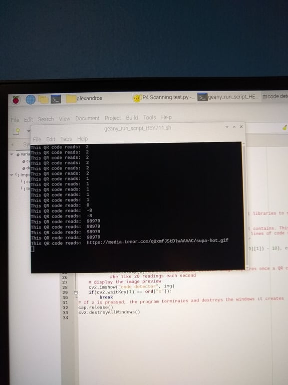
Although our design for this project may seem fascinating, there are still many ways in which it could have been improved. To start, Python is a high-level language. This means that although Python is easy to write code in, it is very slow at performing computational tasks—especially computationally intense tasks such as image recognition. When a sudo top command is run in the terminal to show all current processes, the output-windowless program can use a whopping 188% of the Raspberry Pi’s CPU capacity. Our design could have been improved by writing the program in a lower-level language such as Assembly or C instead. This would have dramatically reduced the time that it takes for our program to scan a QR code. Although using small integers to encode onto QR codes may seem like an intuitive way to make the QR codes as small as possible, and scan as quickly as possible, this may not be the ideal solution given that our scanner took longer to scan a 9cm² QR code of “2” than it did to scan a 6.25 cm² QR code of “98979”. Had there been more time to complete this project, our group would have likely experimented with other small text strings and chosen QR codes that scanned more easily even if our values were not in a numeric sequence.
Barcodes scan much more quickly and reliably when compared to QR codes. Our program would have benefitted tremendously in terms of speed, accuracy, scanning distance tolerance and ease of programming if our group had swapped the camera for a barcode scanner. Project four had less than three dollars left in its budget, and simply swapping the camera for the cheapest commercially available Pi-compatible barcode scanner would have caused this project to run over 50% above the budget. Given that the program that activated our WS2812B lights had to be run manually, our design could be made much more practical by simply wiring white LED diodes to a resistor with jumper cables and connecting everything to the required GPIO pins. While this would forfeit the ability to manually change the brightness and colour of the lights, this would have illuminated the camera and the QR codes without requiring a separate program to be manually activated. Additionally, swapping WS2812B lights for traditional LEDs would have allowed for the scanner program to run on startup. The most obvious way that the design could have been improved would be to implement an on-off switch. To shut down the scanner, the user must unplug the device from the wall. This can cause files to corrupt since it does not give the Raspberry Pi time to properly close the plethora of libraries that it has opened. By adding an on-off switch, the required libraries can be properly closed and the Raspberry Pi operating system can shut down before our client unplugs our device. Each of these last three proposed solutions are glaringly obvious design flaws that would seem incredibly easy to fix, but each of these solutions were not implemented due to time and cost constraints. Even if the order was placed in the first week of project four, some hardware components would not arrive until months after this project was due, which is a result of the aforementioned global semiconductor shortage.
This project showed that one must be independent during the design process and use the resources that are available to them. Project four involved many visits to web forums such as Stack Overflow™ and grabcad.com. It was clear that the TUES-26 group could not rely on resources such as instructional assistant interns (IAIs) and the design studio 3D printers as much as during previous projects. Additionally, this project highlighted the importance of using a variety of tools to get the job done. For example, there are tutorials on YouTube for using the playsound library, using WS2812B lights, scanning QR codes with OpenCV and turning a Python program into an automatically executable script, but this group was unable to find any standalone tutorial that demonstrated more than one of the above actions. Furthermore, there are some niche engineering situations where one must be the first to solve a particular problem. For instance, I was unable to find any information online about fixing the rare error that would occur when the program would draw the bounding box around the QR code. I implemented a simple try...except to reset the camera view, and that just happened to work. The most important thing that I learned from project four is to periodically check in on the people working on the same project as you. Although my responsibilities for this project were limited to writing programs, because I notified the modelling sub-team that they had to design a new case, they were able to take measurements and begin modelling the new case the very next day in design studio. By giving my groupmates regular updates, we were able to overcome this obstacle and barely lose any designing time.
References
[1] “Project four: Power in Community,” P4 Project Module, class notes for ENGINEER 1P13, Department of Engineering, McMaster University, Winter 2023.
[2] Core Electronics, Australia. How To Scan QR Codes With A Raspberry Pi + OpenCV + Python. (Nov. 1, 2021). Accessed: Apr. 10, 2023. [Online Video]. Available: https://www.youtube.com/watch?v=Qf55aUgfLfQ
[3] Core Electronics, Australia. How To Use Addressable RGB WS2812B LED Strips With a Raspberry Pi Single Board Computer. (Oct. 17, 2022). Accessed: Apr. 10, 2023. [Online Video]. Available: https://www.youtube.com/watch?v=aNlaj1r7NKc
 Made with Bullet